 MEMBERSHIP LOGIN
 JOIN PRI
Isky Racing Cams on Valvetrain Maximization—Efficiency vs. Effectiveness
Isky explains the importance of valvetrain efficiency and how to maximize valvetrain stability without sacrificing power.
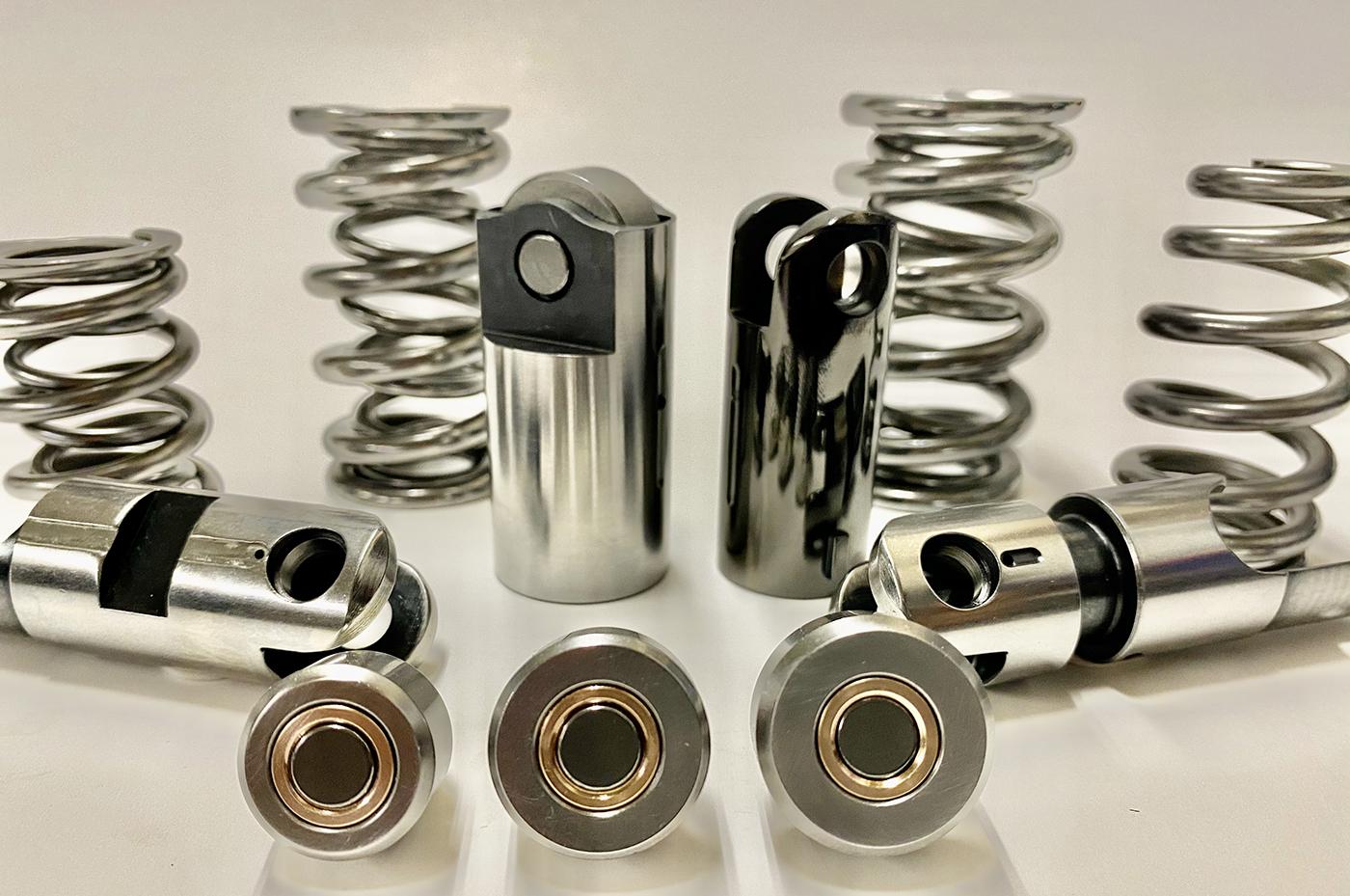
With the EZ Roll Bushing Lifters, and the low friction and high stability inherent in their design, the next step in maximization is the choosing the right springs. We will go over a couple areas to concentrate on that will help when picking the correct spring for your application. The goal is efficiency—not effectiveness!
What we mean by this is you can always throw a ton of spring pressure at a combo that has been having spring problems, and the solution can be effective, but having needless extra spring pressure costs horsepower. It’s better to understand the dynamics of a combo and chose a spring around that.
While we need heavy pressures on the closing side to keep the lifter on the cam and return the valve to the seat, the real stress to the valvetrain is the offset load flex during the wind up of the cam. The load on the parts is at its highest peak off the seat as the valve opens and sends a shockwave from the lifters to the rest of the valvetrain. If you can reduce both spring mass and seat/open pressure while keeping the system in a controlled state—as well as keeping the frictional losses at a minimum—then you are at your most efficient.
Keep in mind when choosing the correct spring it’s always good to talk to the cam manufacturer and go over the cam design to understand the dynamics of the design, and in some instances discuss the elasticity in the different valvetrain parts such as the lifters or rockers.
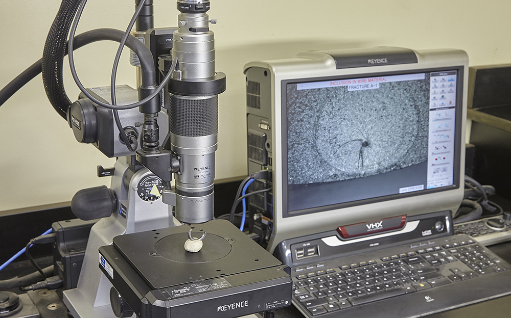
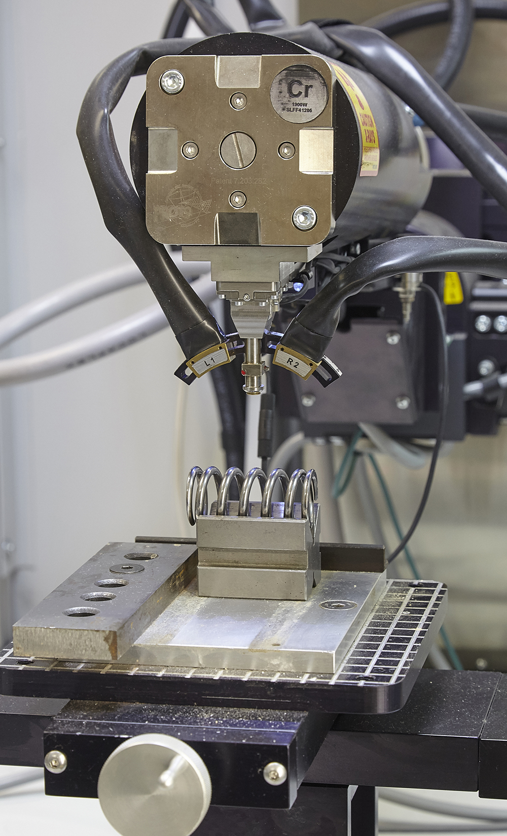
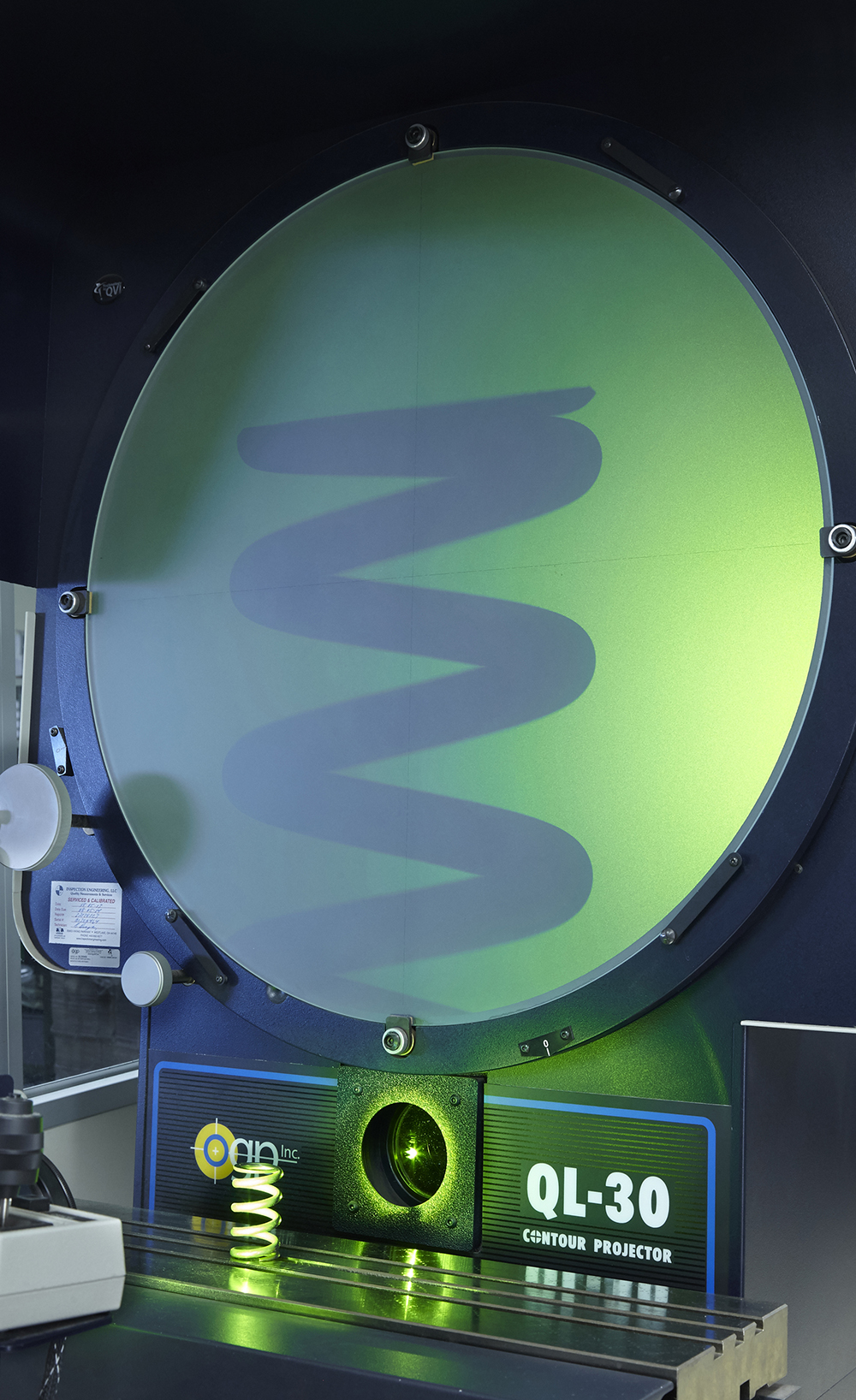
During early Spintron testing of our new Gold Stripe Spring Series, we kept losing needle-bearing lifters as we pushed the limit higher and higher. With the Spintron and laser system, we were able to really see the amount of distortion the roller needle bearing goes though as well as the springs surge wave.
We were also able to see the difference in the designed cam motion and the true valve motion at high rpms and loads. We were shocked to see how much the lifter distorted going up the ramp and also the rebound effect as the valve closed and the effect this had on the springs. This was translating tons of bad harmonics throughout the whole system, limiting performance, and breaking springs. We found that as we pushed the combinations, the needles actually spread apart so much from each other that the main pin would contact the outer wheel race and break it, sending needles through the engines.
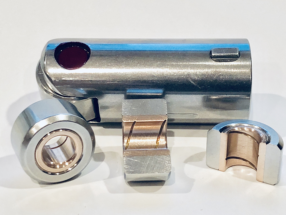
This scenario actually led us to start work on a bushing lifter. A bushing lifter had been tried many times before but no one could get it work. When we finally got the right material mix, we found a lifter that lasted three to four times longer and had 350% more load capacity than any needle bearing lifters we tested. The benefits were undeniable; you could now have a lifter that did not distort under the most aggressive cam profiles and pressures, dampened valvetrain harmonics, and actually gained horsepower!
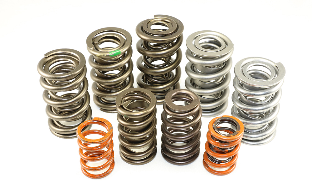
This breakthrough in lifter technology pushed spring design even further. As an example for our high RPM dirt late model engine builders, we introduced our new 1410ML 1.410” Dual w/Damper spring that has 180lbs on the seat and 760lbs open that takes a max lift of .830”. A spring like that was just not possible in the past.
On the other side of the coin for drag applications we have our 1280ML 1.520” Dual w/Damper that has 445lbs on the seat and 1230lbs open that takes 1.000” net lift. These small diameters drastically reduce the mass and the harmonics you have to counteract with the bigger springs. The trend to smaller diameters with big pressure loads is pushing valve spring design to the limit.
The upgrade in bushing lifter technology and pressures they can take allow for more aggressive cams. Better springs are needed for a stable valvetrain in turbocharged, blown, and nitrous applications. Many people ask if you need extra pressure in non-naturally aspirated applications and the answer is yes. In a nitrous application, no extra pressure is needed because it is a direct injection on the other side of the valve, so there is no effect on the seat pressure. This means you are okay covering what the RPM and application needs with no other considerations.
In a blower and turbo boosted setup with very high boost numbers, you should take into consideration that the backside of the inlet valve is under constant static pressure, which diminishes the seat pressure. The question is how much does it diminish, and do I really need to seriously consider it in my valve spring choice? Let’s say you have typical valve diameter of two inches which works out to three square inches of area on the backside. If you have a spring that has 300lbs of seat pressure, a good rule of thumb is to deduct 10lbs per square inch, which equates to 30 lbs. maximum load at RPM and brings the seat pressure down to 270lbs. If you are worried that 270 will not be enough for the RPM, then you would up that seat pressure to counteract that loss. But this would only happen with tons of boost like over 45-50lbs.
For the street guys who add a small turbo with 7-10psi and just bolt it on without new springs, you could run into a problem where 120lbs or even 110lbs on old springs will cause issues that can be fixed with a new higher pressure spring set.
We often get asked if it’s better to set the springs closest as possible to coil bind say within .020”, or farthest as possible like .100” from coil bind. Some top engine builders are able to set the valve springs at around .030”-.040” from coil bind safely because they have measured all through the cam, valve, and rocker motion to make sure there is sufficient clearance at all times and they have tested it on a Spintron and dyno. Below .030” is a recipe for disaster. What many people don’t understand is even at .050”-.070” from coil bind, where we recommend valve springs should be set safely while running at high rpm, spring compression always goes past the coil bind setting. Just because you set the coil bind with a clearance of .060” does not mean the spring actually stops there! Through our experience in Spintron testing, laser measurement, and slow motion video, we see that the coils stack solid. This is a normal occurrence at high RPM spring compression; the coils stack solid. This is why it’s imperative that you use the best material and surface finishing.
Now that you understand the coils will always stack solid past coil bind, the way to get the springs to live is to have the coils stack solid and straight, and not slide out of the stacked line which leads to breakage. This can be controlled by being in that sweet spot of .050” to .070” from coil bind.
On the other side of the coin, why wouldn’t setting up the spring as far away from coil bind as possible be the ticket? The reason is that the further you set up the springs from coil bind, the further you widen the surge area, which creates a better chance at creating surge waves that lead to dynamic instability in the spring. This leads to loss of horsepower and spring breakage. When a spring is manufactured, it is designed with keeping the spring surge to a minimum and by setting them up so far from coil bind you are essentially helping spring instability to occur.
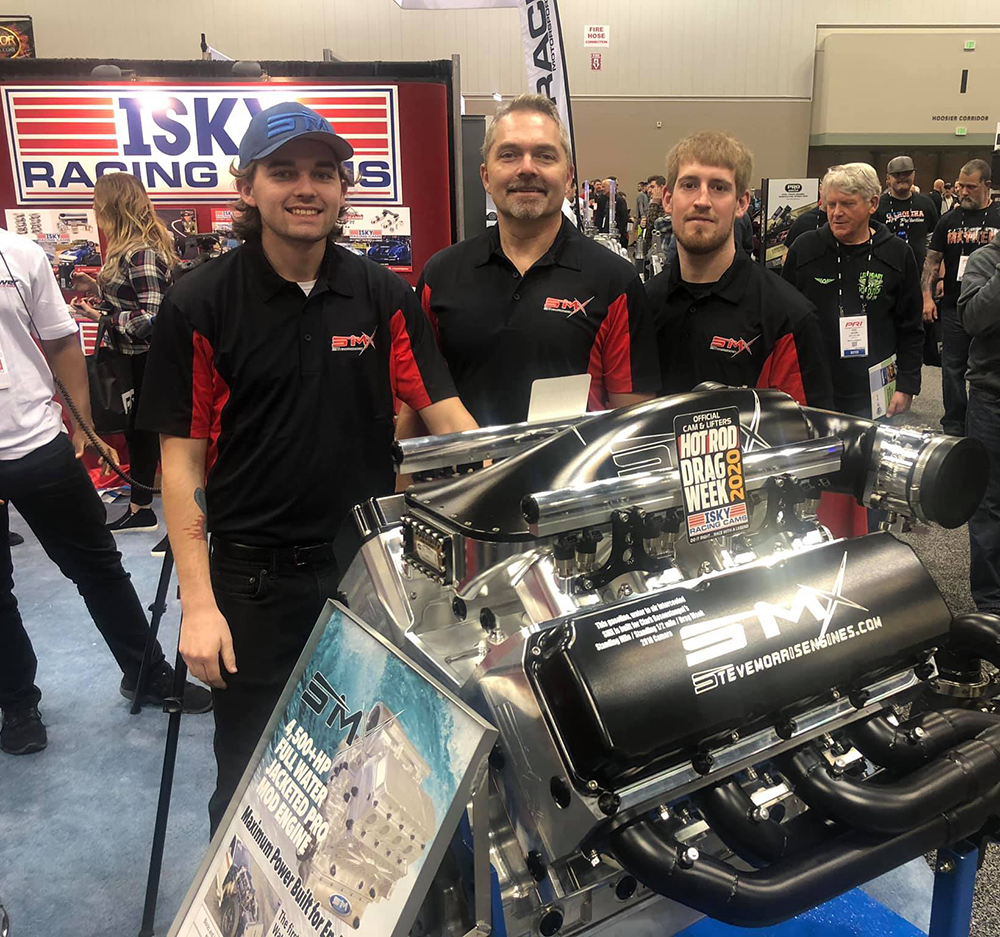
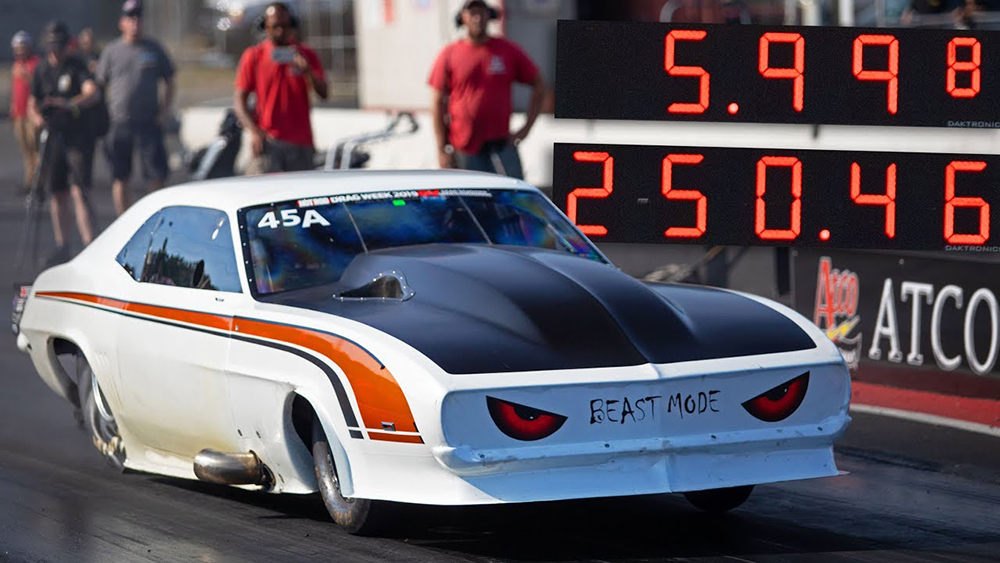
When we work with top engine builders like Steve Morris and his SMX engines, for example, we don’t just want to sell him a set of lifters and springs. We want to understand the whole combination, put our heads together, and come up with a spring and cam design to maximize every area. For Steve, we actually made him a custom offset lifter for his SMX engines that have won back-to-back Drag Weeks with Tom Bailey in his Sick Second Camaro. He broke the six second barrier last year and will go for all fives next year.
Every Drag Week winner in the last few years is running our bushing lifter and spring combo, including Dave Schroeder, John Ens, and Jeff Lutz.
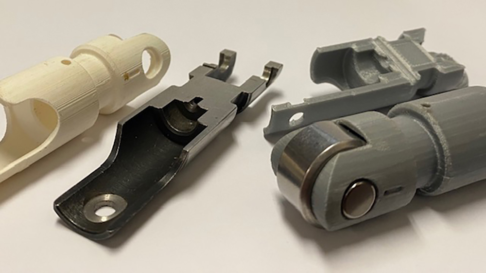
Being able to rapid prototype and 3D print a lifter for mockup has been invaluable for us. When an engine builder wants to change pushrod seat location or relocate an oil hole, we can print and send a sample body the same day so they can see if everything is going to line up. We are looking into a metal 3D printer so the sample body could be run and tested. We make several special lifters for the BA Hemi’s, 481X, and SMX engines and have been working on a new lifter for Pat Musi’s 959 Engines which will debut at the 2020 PRI Trade Show this year.
The goal as always is valvetrain stability at high RPM while keeping the frictional losses to a minimum, which robs horsepower. This can be accomplished by using the bushing lifters in concert with the right spring combo that is setup the correct way. Maximizing valvetrain efficiency is the key to more power and longevity. Happy Hot Rodding! —Nolan Jamora, Isky Racing Cams
The Isky/PSI Maxlife Valve Springs and EZMax/EZ Helix Solid Roller Bushing lifters are available in Tie Bar and Keyway versions for the SBC, BBC, Ford, Chrysler, BA Hemi, 481X, SMX, and Pat Musi 959 engine combos.
For more information, visit iskycams.com.