 MEMBERSHIP LOGIN
 JOIN PRI
Direct Connection
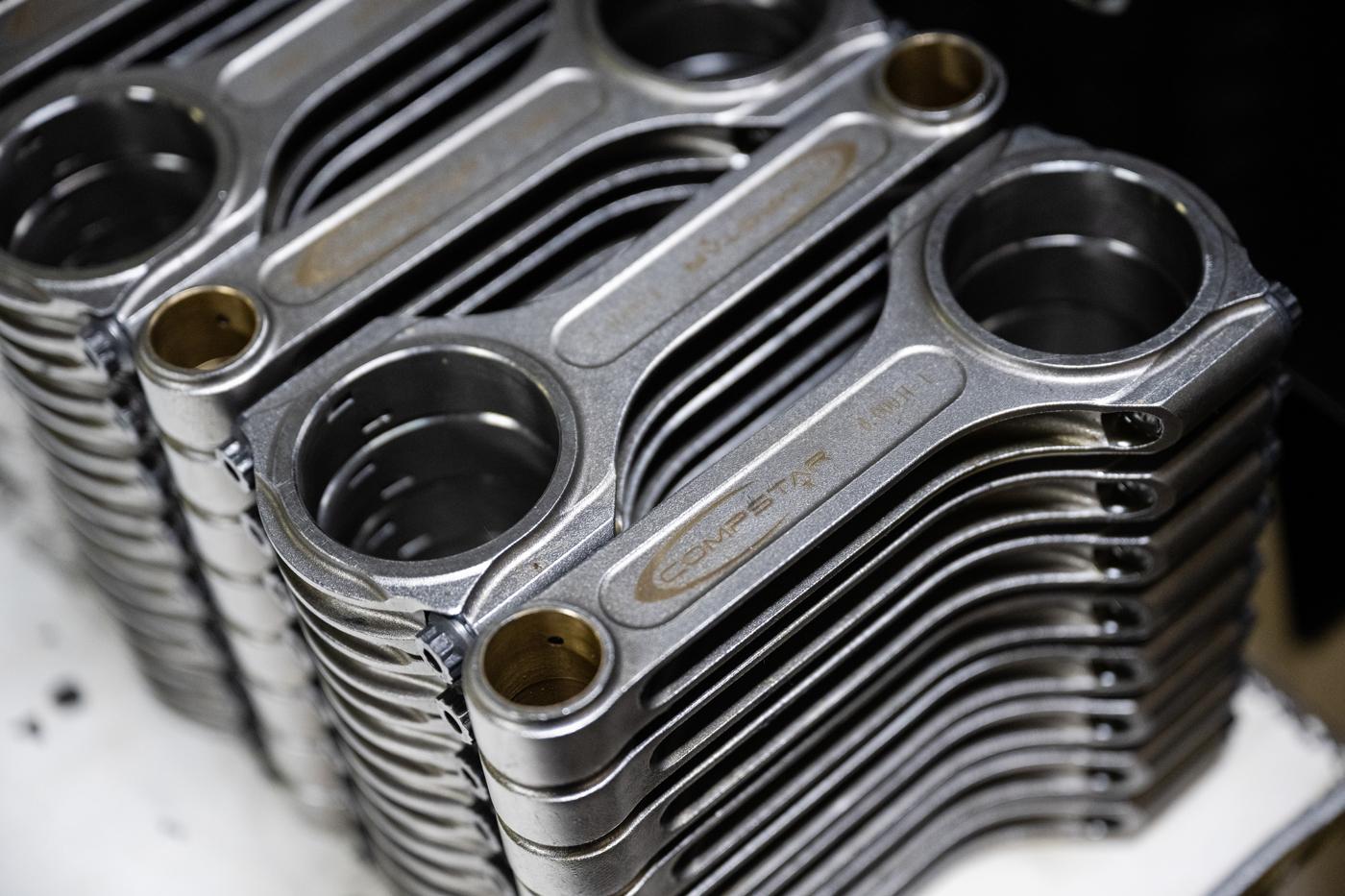
Properly installing rods will help ensure optimum race-engine longevity and performance, and our expert sources are here to provide best practices on securing these critical components.
Connecting rod manufacturers are vigilant in providing detailed installation instructions; yet there’s no surprise in the number of phone calls from customers complaining that the rod is ground zero for some type of engine failure.
“There are engine builders. There are engine assemblers. And there are novices or hobbyists,” lamented Roger Friedman of Dyer’s Top Rods, Forrest, Illinois, stressing that the rod often is only as good as the customer. When they get it wrong, “the rod always gets the blame.”
Perhaps a wide-ranging platform of media options is partly responsible. In addition to the manufacturer instructions, there are dozens of how-to stories featured in enthusiast magazines, tech books, cable TV shows, and Internet forums. Maybe all the attention has made this step in the engine assembly look too easy.
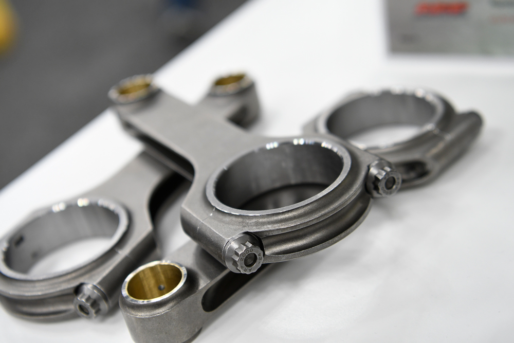
And maybe the best practices don’t always get the attention they deserve. Take, for example, the practice of measuring side clearance between two connecting rods paired on the same crankshaft journal. Sometimes this measurement is called the “cheek” clearance.
This small gap is a way to control the amount of oil lost from the bearings and sprayed on the cylinder wall, wrist pins, and piston. The gap will vary between .010- and .020-inch, depending on manufacturer recommendations and type of rod material. Steel rods don’t need as much clearance as aluminum.
The most popular method of checking the side clearance is with a feeler gauge. Start with a thin blade and work up until the blade just slips between the two rods. Most photos detailing this step show a single feeler gauge being used, and for the most part that approach is adequate for a general-purpose engine build. However, savvy racers will use two feeler gauges to ensure the exact side clearance is measured.
“When using a single feeler gauge, the actual bearing clearance can cause the rod and bearing to cock,” said Tom Lieb of Scat Crankshafts, Redondo Beach, California. “You don’t really get the correct end play.”
Lieb recommended using two feeler gauges of the same thickness to measure the gap 180 degrees from each other. “Say you have .002- to .003-inch bearing clearance. Basically, you will bottom one corner of each bearing against the crankshaft while raising the other side,” explained Lieb. “However, in reality, the bearings move parallel to the crank journal surface. They don’t slide back and forth in a cocked position. If you’re looking for .018-inch clearance, take two .018-inch feeler gauges and measure the gap 180 degrees between the two rods on the crank journal.”
Industry Thoughts
With that in mind, we sampled the industry for the best advice for installing connecting rods. What are the do’s and don’ts of this critical procedure? The connecting rod may appear to be a simple design, but there is considerable technology in choice of materials, methods of construction, and overall structure and configuration. Also, the rod has to work in harmony with the wrist pin, bearings, pistons, and crankshaft, which all have design elements that complement the connecting rod. Improper installation will simply waste that technology. Right away we were faced with a reality check on this quest for wisdom.
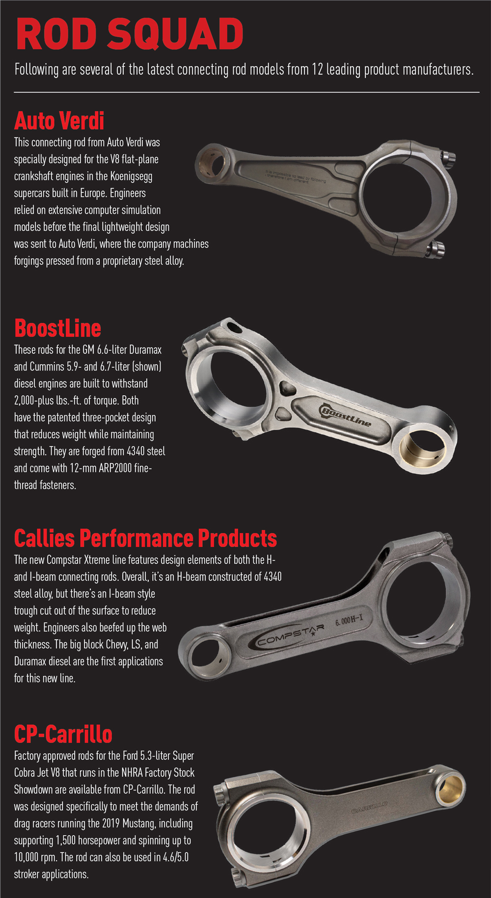
“We deal only in very high-end applications,” admitted Stefan Verdi of Auto Verdi, Söderbärke, Sweden. “So we deal with very experienced engine builders and don’t have problems with installation.”
Okay, let’s start with the basics. Perhaps the most obvious tip is cleanliness.
“Always check the threads and clean the rods before assembly,” said Nick DiBlasi of Race Winning Brands, Mentor, Ohio, which encompasses rod manufacturers BoostLine, K1 Technologies, Manley, and MGP.
“Thoroughly clean components before installation and be sure they are rid of any foreign dirt and oils,” added Matt Polena of K1.
Properly locating the bearings on the rod body and cap is a step often missed in the assembly. “Many high-performance bearings have an ‘upper’ and a ‘lower’ designation, usually found on the back side of the bearing,” said Alan Davis of Eagle Specialty Products, Southaven, Mississippi. “It is important that the upper bearing is installed in the beam portion of the rod and the lower bearing is installed in the cap portion. Installing these incorrectly can cause the appearance of reduced side clearance or possibly causing the bearing to rub on the radius of the crankshaft.”
“People will put them in backwards,” added Friedman, “and then the bearing will hit on the radius of the crank. That’s when they have a bearing failure and blame the rod.”
The position is important because bearings have one edge that is chamfered, and it’s designed to ride on the radius side of the crankshaft. The radius is machined into the crankshaft rod journals to help reduce stress concentrations and improve lubrication at those locations. The other side of the rod is flat and designed to face the matching side of the adjacent rod mounted on the same crank journal.
Some connecting rods are designed with an offset. That is, the big end is slightly offset from the rod beam’s centerline. This is to accommodate engine designs where the centerline of the cylinder bore is slightly offset from the rod-bearing radial centerline. Experienced eyes will notice the offset and install the rods in the correct order. However, depending on the offset and the engine, it’s not always a game-changer.
“The LS engine has on-center rods in the motor. When the LS first came out, nobody was making LS-specific rods, you know, with an on-center beam,” recalled Brook Piper of Callies Performance Products, Fostoria, Ohio. “So, everybody was using small block Chevy rods and never had an issue. Guys to this day still use small block Chevy rods that are offset in a LS application.
“I don’t know that it’s a critical issue,” he continued. “I suppose it would probably mean something if you’re going 300,000 miles. But race-car guys are tearing engines down and putting in new rings and pistons all the time.”
Mixing It Up
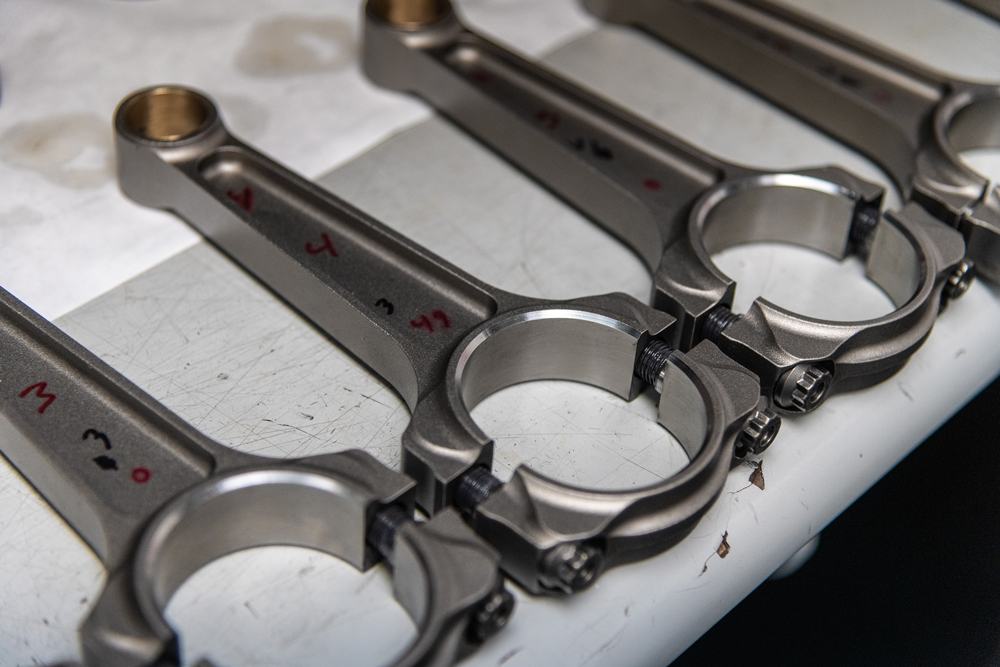
Connecting rods are constructed with the body and caps married to each other. Never mix the caps and beams. Some manufacturers will number match the two pieces in the manufacturing process. If a new set of rods is not already number matched, then mark them immediately upon unpacking.
“But avoid using metal stamps to number rods,” warned Polena. “The rod bore conformity and roundness can be affected by the use of metal stamps. We recommend using layout dye on the cap and rod and scribing or etching the numbers.”
“Also, never flip the caps around when assembling,” added Davis. “This can result in a bunch of problems. They are not symmetrical. Pay close attention to the cap orientation when assembling.”
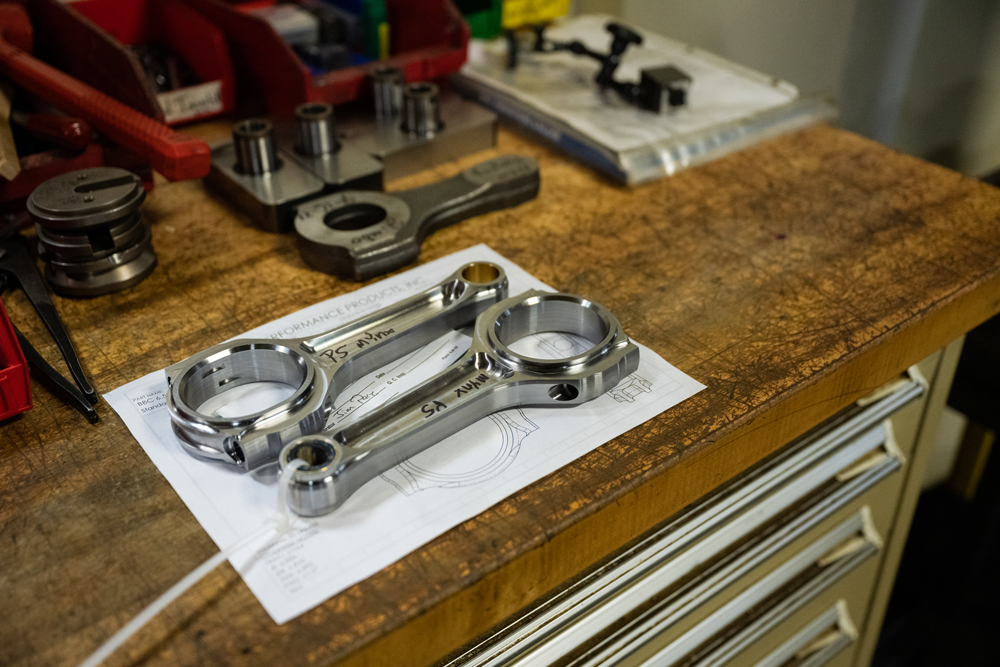
Consistent rod weight is crucial to the balancing operation. However, some engine builders get a little too finicky and may ruin the rod trying to achieve equal weights.
“There are a lot of perfectionists who like to think that every rod should weigh perfectly on both ends. We tell people if they’re within one or two or three grams, please don’t grind on them,” said Friedman. “When you grind on them and look at the metal through a microscope, you see fractures in the metal that will propagate a crack and cause a failure.”
If rods need to be lightened or the big ends need to be narrowed to provide the correct cheek clearance, then call on a qualified machine shop to remove the metal properly. And rods should be matched in weight.
“Never order a single rod without providing the big-end and small-end weights of one of the rods in your set,” advised Davis. “Eagle keeps many single rods in stock, and we can usually match the weight you need very closely. ‘I’ll make it work,’ sounds great until you get a rod that’s 15 grams lighter than your other seven, and then you have to remove 15 grams from those to make a balanced set. If you do not have a record of the weights when the engine was balanced, have a machine shop weigh one for you.”
High Tension
The hottest topic, by far, when discussing connecting rod installation is tightening the cap screws. For some, the practice developed into a precision art that requires purpose-built measuring devices. The days of “torque to 50 ft.-lbs. and then give it an extra tug” are over. The first bit of advice that stands out, is “don’t assume anything.”
“Always double check your torque spec on the rod bolts,” said Will Vance of Lunati, Olive Branch, Mississippi. “Don’t assume it is the same as the original factory part. This is one of the bigger issues, believe it or not, of end users. Most all our rods carry the ARP2000 7/16-inch bolt that holds more torque than an OEM rod bolt. We have call after call where the customer said the bolts were torqued to 45 ft.-lbs. and they say, ‘That’s good, right?’ Most of our products carry a torque spec of 73 ft.-lbs. with lubricant.”
Manufacturers cannot stress hard enough that the proper lubricant is critical to achieving honest and consistent torque figures.
“Each fastener is designed to stretch a specific amount using a specific lube,” said DiBlasi. “Changing that lube dramatically changes the tension and changes the amount of torque required to achieve the stretch.”
“Make sure everything is clean, including the threads in the rods and the bolts,” advised Tom Molnar of Molnar Technologies, Kentwood, Michigan. “Also, make sure the lube recommended by the rod manufacturer is used, and apply the lube every time the bolts are installed, even when checking bearing clearance.”
Ask a dozen top engine builders how they install piston rings, and you’re likely to find 10–12 methods that differ slightly from one to another. The result is the same, but experienced engine builders have their tricks, techniques, and even superstitions that they follow every time. What follows is a sampling of advice for tightening rod bolts from our group of experts.
“We recommend using bolt stretch as the best method,” said Richard Batchelor of CP-Carrillo, Irvine, California. “We’ve added torque angle as the second-best method, since some applications like angled rods have blind holes, and measuring stretch is just not possible. We always tell customers that they should not use torque alone, as it is only measuring the amount of force required to overcome the friction between surfaces.”
“Bolts are nothing more than very stiff springs, and they must be stretched the proper amount to provide the correct clamping load,” explained Molnar. “Since it’s easier to use a torque wrench to tighten bolts, some people will tighten the bolts and note the amount of torque it takes to get to the right stretch then use this value to tighten the remaining bolts. The problem with torque is that it measures friction, not clamping load.
“Since the mating surfaces (threads in the rod, threads on the bolt, spot face on the rod, and flange of the bolt) can change with each tightening, it makes the correct torque a moving target,” continued Molnar. “Measuring bolt stretch is more difficult than using torque, but it is always a more accurate way to ensure the bolts are tightened correctly and helps keep the big-end bores round and to size.”
“It’s a very good idea to record the untorqued, free length of each bolt before use. On subsequent engine tear-downs, compare the untorqued free length of the bolts with their original value,” suggested Davis. “If you see any change, it is time to replace the bolts. This is the very best way to evaluate the condition of the rod bolts. Just going by ‘number of runs’ or something obscure like that is not accurate at all. Different engines have wildly different stress levels. It is impossible to gauge the life of rod bolts with any accuracy based on how many times they have been run.”
Steel rods have taken up all the discussion so far, but there are racers running aluminum and titanium rods to lower the rotating weight. Following are a couple of tips for these materials.
“It seems to be much more prevalent with aluminum rods to see installers intentionally over-torque the bolts to achieve greater clamping force, say 130 ft.-lbs. versus the recommended 105 ft.-lbs. The concern here is stress on the threads and crank bore distortion,” cautioned Michael Tokarchik of Manley Performance Products, Lakewood, New Jersey, which recently absorbed the manufacturing duties of MGP Connecting Rods under the Race Winning Brands corporate umbrella.
“When installing titanium rods, the setup is almost the same as steel as far as clearances and the like,” said Peter Harris of Crower Cams, San Diego, California. “The biggest problem we see with installation is sneaking up on the bolt torque. They’ll torque them to 10, then 20, then 30 and so on. Titanium tends to grab the bolt doing it this way, and then you’ll run into bolt problems down the road. A titanium rod wants a well-lubricated bolt and one sweeping motion to the recommended torque.”
Not sneaking up on the final torque number is also good advice for users of steel rods.
“I have explained to customers that going in small increments, such as 2 to 5 ft.-lbs. at a time, is not a good idea. It may take that just to overcome the friction, and you may not have actually moved the bolt,” warned Batchelor. “We had a customer who was only going up 2 ft.-lbs. at a time. He reached our max torque and stopped, not realizing that the bolts were under-stretched. Because of that, this resulted in a premature failure of the bolt.”
And the customer probably at some point blamed the connecting rod for the failure.
While the connecting rod is simple in design and function, care must be exercised when installing them. Actual connecting rod failures are rare in motorsports. If a rod bends or breaks, it’s almost always due to improper installation or another contributing factor, such as poor lubrication or severe detonation.
Sources
Auto Verdi
autoverdi.com
BoostLine
boostlineproducts.com
Callies Performance Products
callies.com
CP-Carrillo
cp-carrillo.com
Crower Cams & Equipment Co.
crower.com
Dyer’s Top Rods
dyersrods.com
Eagle Specialty Products
eaglerod.com
K1 Technologies
k1technologies.com
Lunati
lunatipower.com
Manley Performance Products
manleyperformance.com
MGP Connecting Rods
mgpconnectingrods.com
Molnar Technologies
molnartechnologies.com
Scat Crankshafts
scatcrankshafts.com