 MEMBERSHIP LOGIN
 JOIN PRI
Stop Doing That…Do This Instead: Sensor Placement
Exposure to heat can affect sensor operation, which is why Chris Johnson of JMS Chip advises maintaining “a foot of distance between any heat source and a sensor.” If that’s not possible, “that’s where I would build shields,” with sleeves on the wiring to the sensor and a wrap around the heat source.
Taking a calculated approach to installation can improve these components’ longevity and yield more reliable data.
Data acquisition has become an indispensable resource across myriad different motorsports disciplines. Whether it’s the driveshaft speed and shock position of a drag car, or the steering angle and throttle position of a sports racer, this technology can provide a wealth of information to help dial in a setup or identify potential issues. But to get the most out of it, the data needs to be as reliable as possible, and much of that comes down to how and where the system’s sensors are installed on the car.
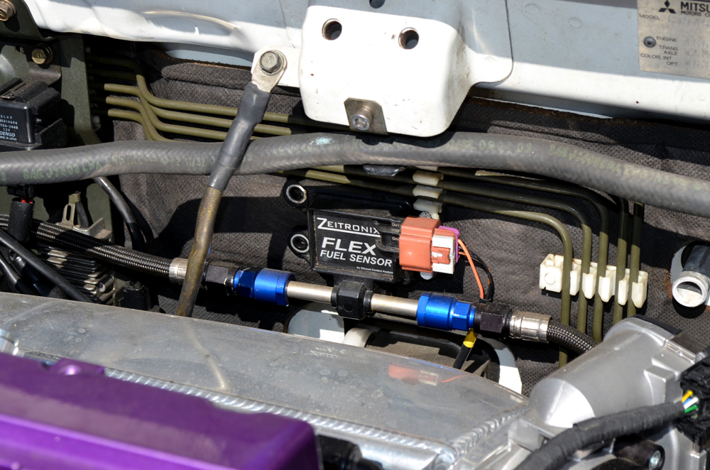
As Scott Gilman of Trensor, LLC in Irvine, California, pointed out, there’s no universal rule of thumb to sensor placement and installation, so it’s important to start with a product that’s purpose-built for the application. “One of the most common mistakes we see from racers is that they’ll place several engine-related sensors in a box that is mounted nowhere near that engine, and they’ll have tubes or braided lines going from that box over to the engine.”
Gilman said that this is typically done because the sensors that are being used aren’t designed to withstand the amount of vibration that they’d be subjected to if they were mounted directly on the engine. Rather than seeking out the appropriate sensors for the application, some will attempt to address the problem by placing the sensors in a spot that isolates them from those vibrations, but doing so can introduce other problems.
“By moving the sensor away from the source, the lines are allowing for pressure drop, and they can also act as a heat exchanger,” he added. “That means that the sensor isn’t getting an accurate picture of what’s going on.”
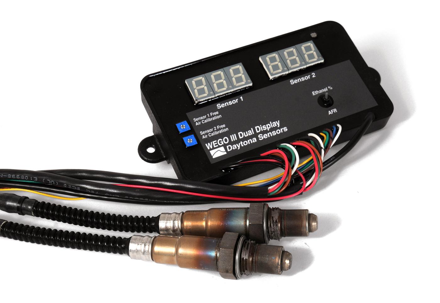
Chris Johnson of JMS Chip in Lucedale, Mississippi, said that the orientation of a wideband O2 sensor can have a significant effect on its longevity and accuracy. “We often see people mounting these in the 4 o’clock to 8 o’clock position (with ‘straight up’ being at the 12 o’clock position). That’s a problem because water will start to puddle up on the sensor whenever the engine isn’t running, and that will be detrimental to the life of the sensor.”
He also told us that excessive exposure to oil and antifreeze will damage wideband O2 sensors, and many times they’ll provide false readings before failing entirely. Ideally, these sensors should be oriented in a position between 10 o’clock and 2 o’clock in order to minimize the potential for water to collect in the sensor. Johnson added that the sensors should also be located somewhere that’s relatively easy to access.
“When you crank an engine for the first time, you’re probably going to want what I call ‘startup sensors’ in there because those sensors will likely be exposed to oil, water, and other contaminants during that initial startup. If you want data that’s as accurate as possible, those sensors need to come out once the engine is warmed up and replaced by sensors that are known to be good,” Johnson said.
Gilman said that upward orientation can benefit sensor longevity in other ways, too. “If you know a sensor is going to get a lot of gravel and other debris kicked up on it, you want to avoid mounting it in a downward orientation in order to minimize the chances of the sensor taking a direct impact.”
He also cited inadequate wiring lengths as another common issue. “Strain relieving is hugely important in racing applications. For instance, if you have a sensor that’s mounted to an engine and a wire harness that is mounted to a tube chassis, you have to consider the fact that those two things are vibrating and moving in different axial planes. The engine may be shaking side to side, whereas that chassis may be flexing up and down. We often see frayed or broken wires, pin damage, and other wear at sensor connection points because the length of wire being used is too short, and that can cause the signal to drop out intermittently.”
To avoid the problem, the wire should be long enough so that it can’t be pulled taut by the movement of components that can happen at speed. The amount needed can vary significantly based on the situation, but Gilman advised that 5 to 7 inches of extra wire would likely be appropriate in most cases.
Exposure to heat is also a vital consideration when installing sensors. “It’s a big concern—I would want to see a foot of distance between any heat source and a sensor,” Johnson stressed. “But there are situations where that may not be possible, so that’s where you would build shields. I typically won’t wrap the sensor itself because you want to be able to get to the connector, but I’ll sleeve the wiring going to it, and also wrap the heat source.”
Sources
JMS Chip
jmschip.com
Trensor
trensor.com