 MEMBERSHIP LOGIN
PRI Tech: Stepped Pipes vs. Straight Pipes
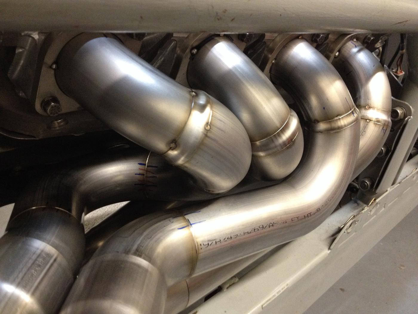
Most stepped headers feature sharp steps. This Bonneville big block header uses smooth transitions that are required for thin wall exhausts (0.035-inch wall or less).
While stepped headers may offer improved power and power band, some applications are nonetheless better suited to a straight design.
How do you get maximum performance out of your exhaust header?
For starters, an effective exhaust system optimizes the movement of the pressure waves occurring within it. Pressure wave management helps maximize “mass-flow.” Mass-flow is the process of moving the largest amount of exhaust gas out of the header as efficiently as possible. Performance header design focuses on optimizing mass-flow.
During camshaft overlap in the cylinder head, vacuum waves resulting from pressure wave reflections in the engine’s exhaust ports function to extract exhaust gas out of the cylinder. To maximize mass-flow, there are key aspects of header design that affect both the timing and strength of these pressure waves. They include:
• primary length
• primary diameter
• collector size
• tail pipe size
These components are 95% of the qualitative game.
The question now becomes, “What exhaust header design offers the best performance—stepped or straight?” Let’s first break down their differences.
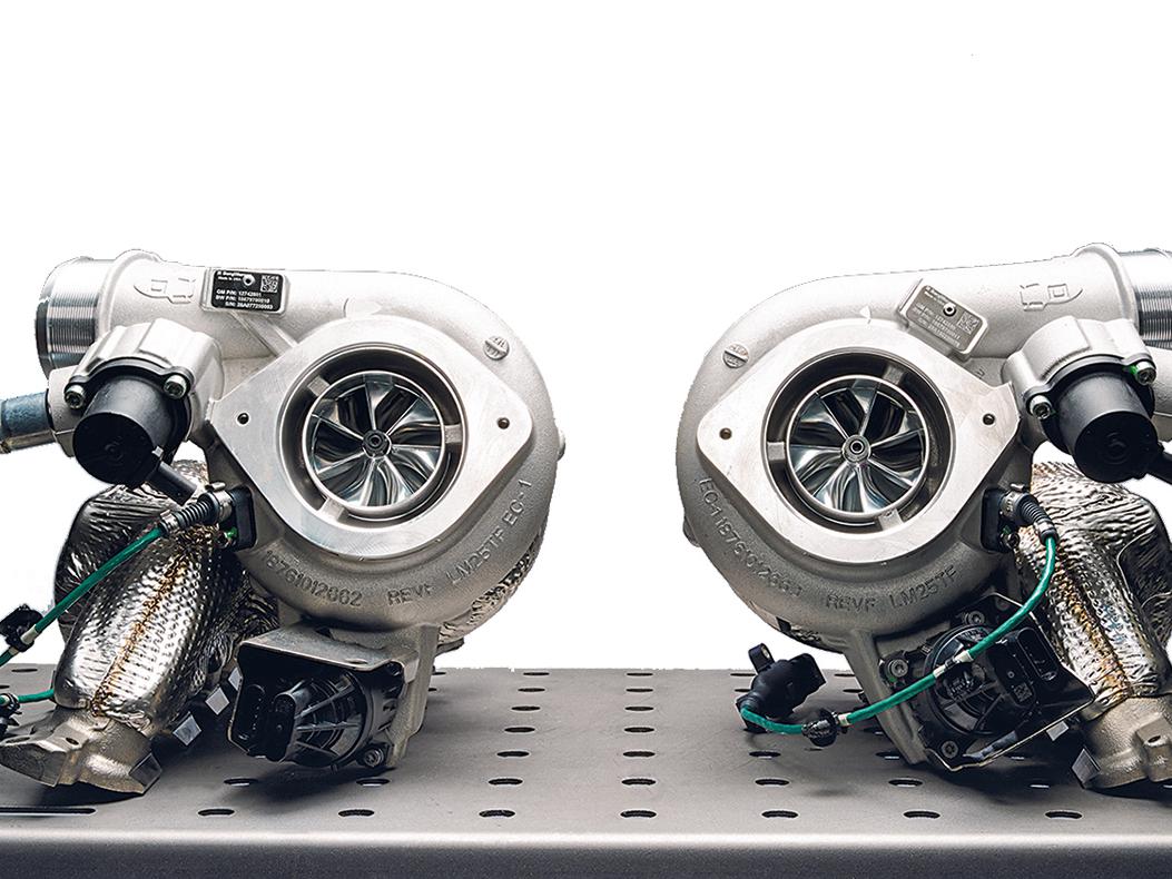
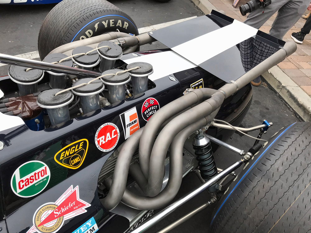
Straight-tube headers have constant diameter tubes that flow exhaust from the engine to the atmosphere. By contrast, a stepped header has exhaust tubes that increase in size as they get farther from the exhaust ports. These “steps” are typically spaced in 1/8-inch increments.
Stepped headers may provide another 5% of improved power and power band by further managing the flow and wave dynamics. That’s not to say you will see a 5% increase in max power output, but rather an increase of 5% in the total of any performance gained from the entire exhaust system.
Pressures and Wavelengths
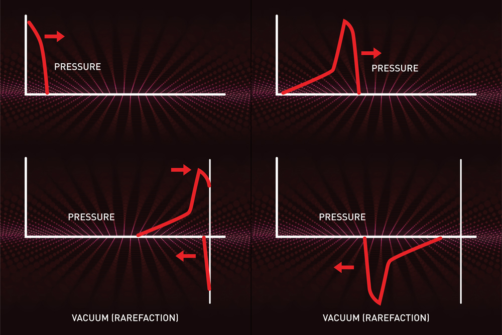
To explain how stepped design improves flow and power range, let’s review what happens in the header. As the exhaust valve opens following the power stroke, a pressure wave and a mass of exhaust gas flows from the cylinder into the header primary. The graphs on page 97 help to illustrate this process.
The pressure wave generated travels at near the speed of sound. In the case of a constant diameter tube without a collector, the wave hits the end of the tube, and a negative pressure (i.e. vacuum) wave reflects up the tube. The reflected negative wave is the result of the “boundary condition.” This is the constraint point at the physical end of the system. In this case, it is the exhaust tip(s) or exit point of the tube. At this boundary, the pressure must equal atmospheric pressure, giving rise to a balancing negative pressure wave.
Using the speed of sound value calculated by the temperature and composition values of the exhaust gas flow, we can understand the time required for a pressure wave to travel the total length of the tube.
The goal is to time the exact speed the pressure waves will travel from the exhaust valve to the end of the pipe. That value is then combined with the value of the resulting vacuum wave traveling back to the exhaust port. When these two combined values are equal to the time of one crankshaft revolution for a set engine speed, it is known as the “tuned rpm.”
Tuned RPM and Exhaust Scavenging
At the tuned rpm, this wave will enter the cylinder during the cam overlap period. This will “suck,” or scavenge, residual exhaust out of the cylinder, helping the intake charge to fill the cylinder. A straight open-ended tube for each cylinder will create the strongest possible wave reflection from the end of the tube.
However, a problem arises when the engine rpm is “off” the tuned rpm of the pipe. The wave reflections can disrupt the cylinder from scavenging and filling. Consider: At an off-tuned rpm, vacuum waves may reach the exhaust port when the valve is closed. This results in a positive wave reflecting from the end of the tube. If this wave arrives at the valve during cam overlap, the exhaust gas flow becomes restricted. The result is a narrow tuning range resulting in a “peaky” power band.
With a stepped header, the smaller tube size near the port provides a higher gas velocity. This allows the exhaust to evacuate further while the exhaust valve is open. The larger tube size downstream reduces the pressure drop through the header, thereby improving mass-flow through the tube.
Creating Broader Power Bands
In addition to the above, the stepped design also creates multiple wave reflection points. These smaller vacuum waves help evacuate exhaust from the cylinder at different engine speeds. This results in improved torque across the power band.
These multiple reflections also reduce the strength of the positive wave traveling to the end of the tube. This results in a smaller-sized primary scavenge wave.
Due to the amplifying effect of frequency resonance, these waves will still have enough scavenging strength at the tuned engine speed. Yet, the reduced strength of the waves will cause less havoc at other engine speeds. This again results in an increased range of the power band. In a perfect world, a constantly tapered exhaust primary tube would be ideal. This would distribute the reflected waves infinitely over the length of the primary tube.
Bigger Isn’t Always Better
There are many benefits to a stepped exhaust header. One practical benefit is that the exhaust tube is smaller at the cylinder head. This is often easier to package in a full chassis car. It’s the reason racers likely developed this design in the first place. Yet, the most important benefit is its performance improvement over straight-tube designs.
So, when money is no object, then a stepped pipe is better, right? Well, no, not always.
Remember what we said earlier: Two of the most important aspects are the primary and collector diameters. Oftentimes, engines have exhaust ports that are too large. This is especially true in vintage engines and lower-performance modern engines.
In general, engines dislike tubes that are reduced in diameter. If the exhaust port is larger than the ideal primary size, building a stepped pipe will result in the primary and collector being too large. This results in inferior performance.
Cost and Application Considerations
Stepped-header tubes are also more difficult and more expensive to fabricate than straight-tubed headers. So, if you do not need to extract all the power available, then a straight-tube header is going to get the job done.
Which is to say that stepped headers are often—but not always—the best solution.
We do find that for well-developed modern race engines with properly sized exhaust ports, a three-stepped exhaust primary is best. For example, the ideal header size for an LS7 crate motor would be a 1 3/4-inch + 1 7/8-inch + 2-inch OD stepped primary. In comparison, a lower-performance LS3 crate engine with similar-sized ports is 1 3/4-inch OD.
The fluid dynamics and thermodynamics occurring in the exhaust of an internal combustion engine are extremely complex. Explaining them fully in this space is simply not possible. Instead, the goal here is to help you develop a visual understanding of what is occurring in the exhaust system and assist in guiding you to the best solution for your performance build. P
As the owner of Burns Stainless, a manufacturer of racing exhaust components, Vince Roman has designed exhaust systems for more than 20 years. Prior to working at Burns Stainless, he was a research engineer working in combustion phenomenon and air pollution control. Roman has a BS and MS in Mechanical Engineering from the University of California Irvine.