 MEMBERSHIP LOGIN
PRI Tech: Race Engine Valve Wear
This kind of valve wear is common in street and race engines due to the fact that this part of the valve is one of the least lubricated areas of the whole engine. The situation is worse in a race engine, as higher loads and increased engine speeds can sometimes break the oil film, causing metal-to-metal contact.
High rpm, elevated exhaust temperatures and other operating conditions a race engine experiences can lead to premature valve wear. Here are some typical valve wear problem areas and their root causes.
In the race engine world, valve wear issues may not always be fully understood. Most wear patterns are typical for any kind of engine valve, but due to the higher rpm, high-power density, higher exhaust temperatures, and bigger loads that race valves are subjected to, they can be found more often in race engines than those on the street.
Abnormal wear is only the initial step of what could be a more serious valve failure. That’s why it is so important to check your valves after each race (or several races, depending on the class or engine usage).
The forces acting on valvetrain components, due to camshaft push and inertia forces, are loads transmitted to small contact surfaces. Even though we see a whole valve stem or a whole valve seat, the contact surface between the mating parts is usually a thin line, or a very small area. As a result, the materials must resist compressive stresses.
Below are some typical race engine valve wear examples. Note that different sections of the valve usually show very different wear patterns.
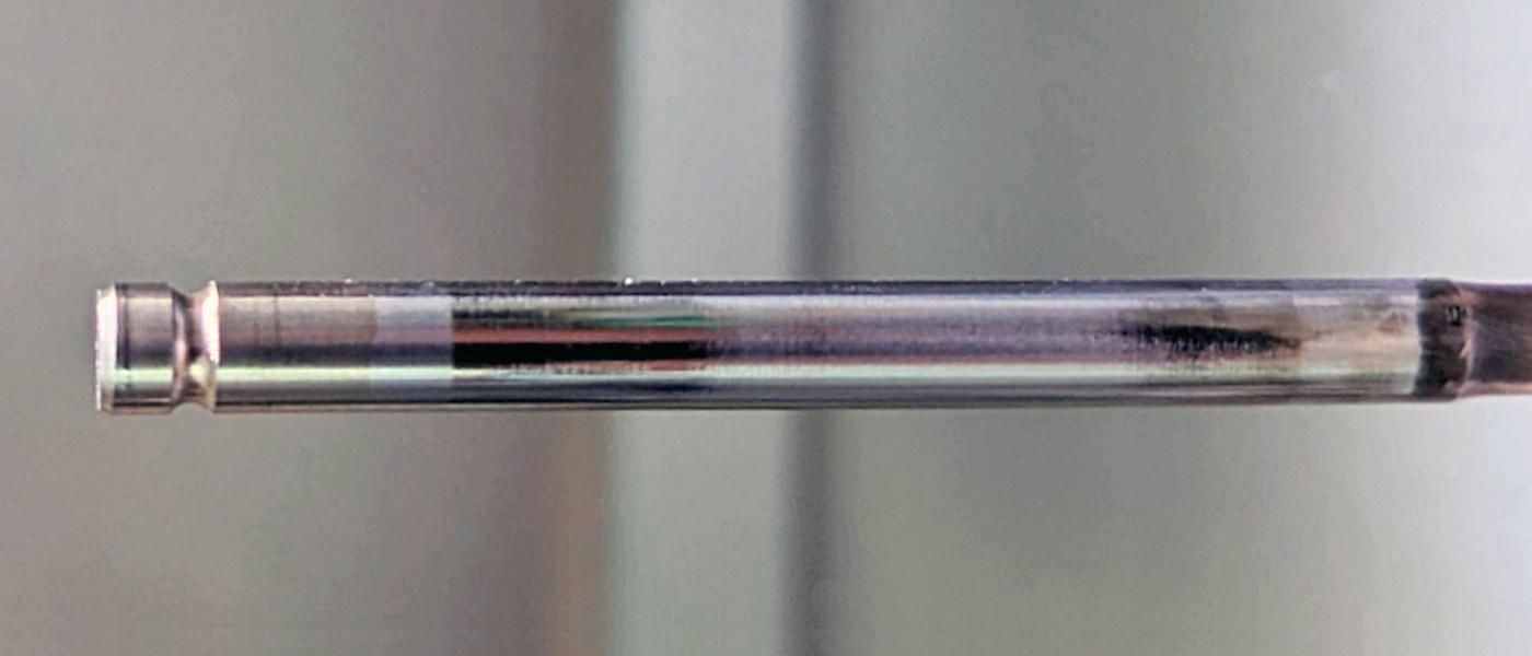
Valve Stem Wear
This is perhaps the most common valve wear seen in any street or pure racing engine. This valve area is one of the less lubricated areas of the whole engine because the valve guide/valve stem clearance is very low, and emissions regulations have led to less oil flowing down the guide to the combustion chamber. This situation is even worse in race valve applications due to the higher loads and increased engine speeds that sometimes break the oil film, allowing direct metal-to-metal contact.
There are several possible root causes for these wear patterns. Among them is valve stem-to-guide clearance that’s too small at assembly. This is usually an exhaust valve issue because they run much hotter than the intake valves, which leads to stem thermal expansion.
The side loads present in a typical pushrod or finger-follower stem valve can create wear, mainly when higher lifts are used that create loads at the tip that push the valve sideways against the guide, creating a localized contact area of higher stress.
Bad valve guide concentricity with the seat insert can also cause wear, as it generates high side loads due to misalignment. At high rpm this misalignment is often the root cause of broken valve stems due to the repeated bending of the head.
Oil starvation due to low oil pressure could create valve stem wear patterns, as could a lack of material compatibility between the valve stem material (or coating) and the valve guide. The scuffing that can result, if not found in time, leads to galling, with guide material adhering to the stem. This could cause a sticking valve inside.
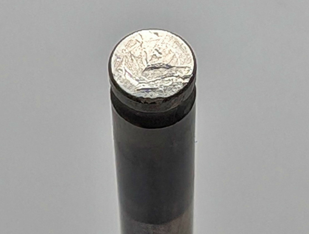
Valve Tip Surface Wear
In most of the racing engines we work with, increasing rpm and aggressive camshaft profiles create heavily loaded zones at the valve’s tip surface, with high concentrated contact stresses and impact loads at the opening side of the cam profile. Voids may occur at the surface, and cracks can further propagate in the material. Pitting is also found at the tip surface as a result of the same mechanism.
Sometimes, when the rocker arm radius has been modified or is too small, the contact zone at the tip is so small that the concentrated load raises the working stress beyond the material yield stress, creating a void or a big depression.
If these wear patterns are found, check with the valve supplier for the appropriate engine application regarding engine rpm, valve lift, and tip protection. (In some cases, hardened lash caps are recommended.)
Excessive valve lash is another possible source for “tip hammering” that usually leads to tip wear and deformation.
Bad rocker arm geometry, especially with higher valve lifts, sometimes extends the roller or rocker arm tip path across the valve tip, overpassing the border and pushing against the valve tip chamfer, rounding and deforming it, and creating a lateral load on the stem end.
Also check for weakened or inappropriate valve springs, or engine over-revs due to a too-short final gear ratio for a particular track. With rev limiters so popular in today’s racing engines, if the on-and-off “hammering” is allowed along a long straight, it could damage a valve tip, not to mention the valve seat suffering.
Another pattern of tip wear is usually found when valves don’t rotate. When the rocker arm works on the same back-and-forth path, it creates a visible wear line. This path is not detrimental as long as it stays only “visible,” but it could become a problem if the rubbing action creates wear or a channel on the tip. (A similar “path” is often seen at the lifters when they don’t rotate, very likely causing cam wear.)
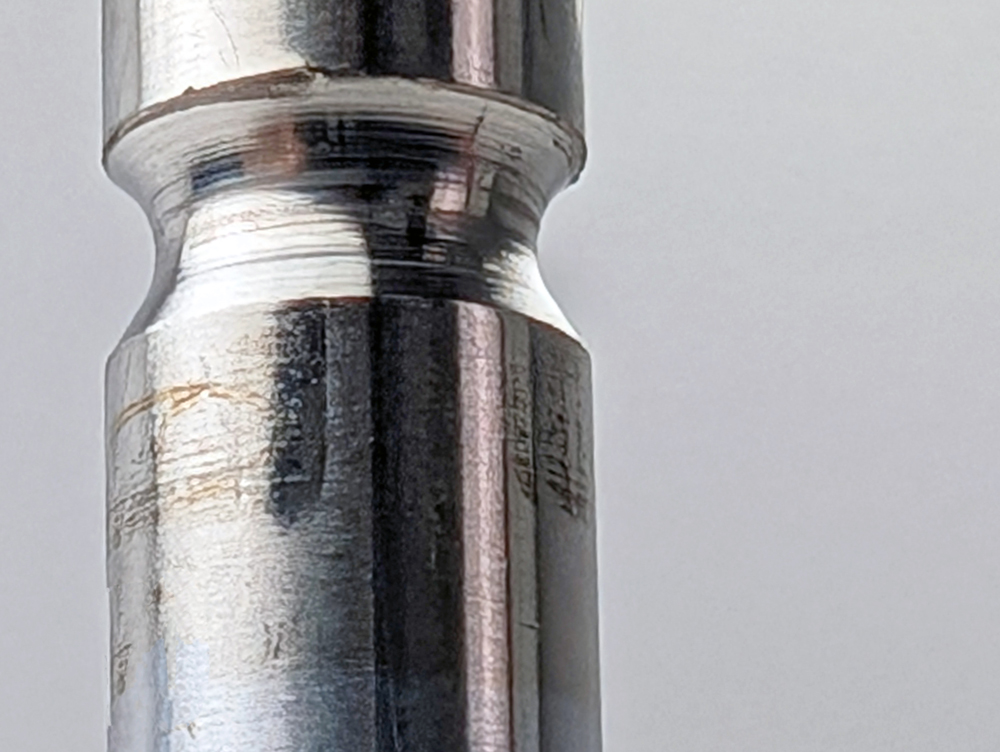
Valve Groove Wear
This is usually an overlooked area that did not receive enough attention after cylinder head disassembly. Marks and scratches inside the grooves are indications of locks touching inside the lock’s inside diameter, not matching properly and creating a complex stress condition that would lead to accelerated wear or breakage at the inside diameter of the groove.
Another wear source at the groove area is also found in over-revved engines, because the abnormal and repeated impacts at high rpm produce high frequency vibrations that loosen or break the locks, allowing relative motion, tilting retainers, and eventually lost retention, with the valve falling inside the chamber.
Valves with multiple round grooves are allowed to rotate inside the locks to enhance valve rotation. If the valve at the groove area is not hardened enough, or made from a softer material than the locks, the rotation will increase the wear rate inside the grooves.
Valve Seat Surface Wear
The seating surface area is the most complex zone regarding valve and valve seat insert durability. Temperatures here can reach 1,800–1,900 degrees F, mainly due to the popularity of turbo or supercharged applications, aggressive fuels, impact loads at high rpm, and so on.
Things get worse with the trend toward lighter valves in an effort to reduce valvetrain inertia forces as a means to increase rpm and power. The heads of these lighter valves can be more flexible under high-combustion pressures, resulting in a sliding motion at seating.
Combined with valve rotation and the other factors we’ve mentioned, each case must be carefully studied, and all mating parts thoroughly inspected, to understand why unusual or premature wear patterns could have happened.
The most common reason for valve seat wear in racing valves is excessive mechanical loads, meaning seating velocities that are too high due to camshafts that are too aggressive for the springs being used (or weakened springs), engine over-revs during some period of time, or a badly machined camshaft with chatter marks that create high frequency vibrations. In many cases you’ll find a somewhat “rounded” seat surface due to the repeated pounding of the valve against the valve seat insert.
Seat wear can also be due to bad alignment between the guide centerline and valve stem due to a lack of concentricity during head machining and guide installation. This forces the valve to work crossed, increasing the contact loads on a sector of the seat surface. The higher contact stresses, in connection with high exhaust temperatures, weaken the valve material, producing loss of material and the formation of voids. The valve’s rotation quickly advances the wear around the whole seat circumference.
Another cause is a lack of tribologic compatibility between the valve seat and valve seat insert materials for the fuel being used and combustion temperatures. When very high temperatures are present, we need to use valves with higher temperature resistance (like Inconel, or in extreme cases adding PTA Stellite welded to the seats), as in many heavy-duty diesel engines. This material has a higher hardness at high temperatures than regular steels or titanium.
It’s common to see intake valve seat wear when the air filter is not fitted, or fitted improperly, or is too dirty or blocked to function properly, allowing hard particles and fine dust to enter the intake runners and get trapped between the valve and valve seat insert. With some valve rotation, this condition quickly wears out the surface, scratching it and even polishing it, but several thousandths deep.
We at Supertech are ready to help our customers find out what could have gone wrong in any race-oriented engine valve wear issue.
CEO Willy Tagliavini founded Supertech Performance in 1999. Tagliavini earned his mechanical engineering degree from the University of Buenos Aires in Argentina. Supertech specializes in high-performance racing valves and engine components.